DDM, the Digital Devices Manager, is the configuration utility for the headend.
The current version of DDM is available on this website:
These operating systems are supported:

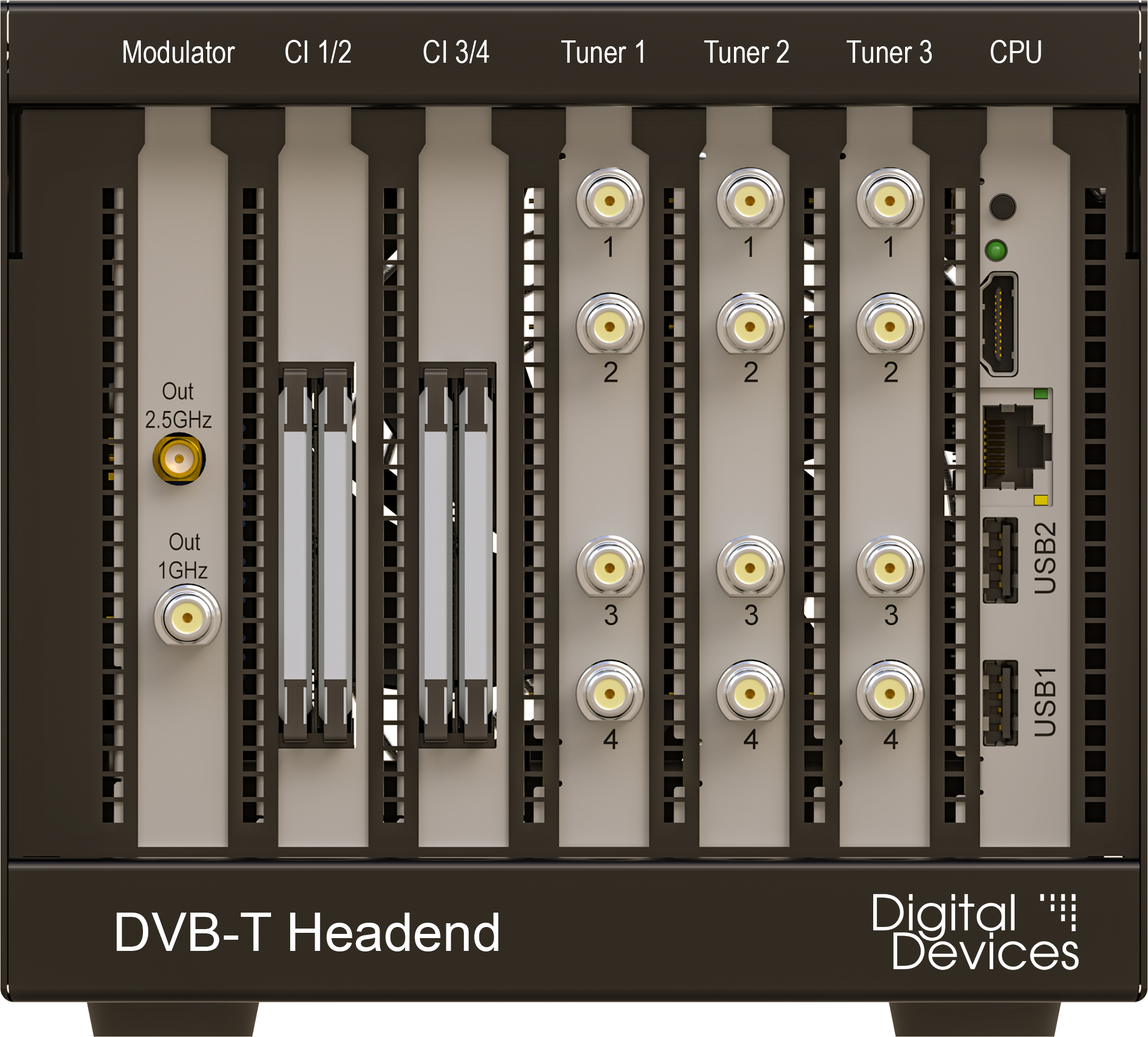
| Tuner 1 | Tuner 2 | Tuner 3 | Signal |
|---|---|---|---|
| 1 | 5 | 9 | vertical lower |
| 2 | 6 | 10 | vertical upper |
| 3 | 7 | 11 | horizontal lower |
| 4 | 8 | 12 | horizontal upper |
| Tuner 1 | Tuner 2 | Tuner 3 | Signal |
|---|---|---|---|
| 1 | 5 | 9 | LNB / multiswitch port |
| 2 | 6 | 10 | LNB / multiswitch port |
| 3 | 7 | 11 | LNB / multiswitch port |
| 4 | 8 | 12 | LNB / multiswitch port |
| Tuner 1 | Tuner 2 | Tuner 3 | Signal |
|---|---|---|---|
| 1 | 5 | 9 | Unicable |
| 2 | 6 | 10 | not used |
| 3 | 7 | 11 | not used |
| 4 | 8 | 12 | not used |
| Tuner 1 | Tuner 2 | Tuner 3 | Signal |
|---|---|---|---|
| 1 | 1 | 1 | vertical lower |
| 2 | 2 | 2 | vertical upper |
| 3 | 3 | 3 | horizontal lower |
| 4 | 4 | 4 | horizontal upper |
| Tuner 1 | Tuner 1 | Tuner 1 | Signal |
|---|---|---|---|
| 1 | 1 | 1 | LNB / multiswitch port |
| 2 | 2 | 2 | LNB / multiswitch port |
| 3 | 3 | 3 | LNB / multiswitch port |
| 4 | 4 | 4 | LNB / multiswitch port |
| Tuner 1 | Tuner 2 | Tuner 3 | Signal |
|---|---|---|---|
| 1 | 1 | 1 | Unicable |
| 2 | 2 | 2 | not used |
| 3 | 3 | 3 | not used |
| 4 | 4 | 4 | not used |
This section describes the initial setup of the headend. This includes configuring the host name, the IPv4 addresses and setting a password.
For setup with DDM, the headend must be in the same LAN as the PC. Alternatively, a graphical user interface and a command line shell are also available on the console of the headend. In this case, however, an HDMI monitor, a USB keyboard and, for the GUI, a USB mouse are required.
For initial setup with DDM, the headend must be in the same LAN, i.e. there must only be switches but no routers between DDM and the headend. IPv6 must be activated on the computer with DDM.
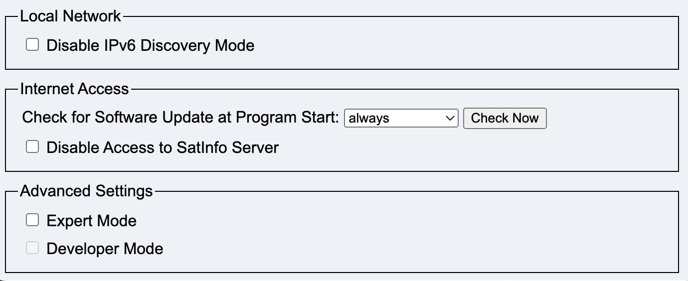
The headend sends an IPv6 multicast packet immediately after a restart. This is repeated ten times at seven-second intervals, after which only one packet is sent every 70 seconds.
The IPv6 Discovery button can be used to directly request a response from headends.
As soon as the DDM recognizes a new headend, it is entered in the device list and a connection is established. If the device is not configured to the default password, a pop-up window appears for entering the password.
A click on Setup opens the setup window of the headend.
The fields Label and Location can be used to identify a headend if there are more than one entries on the list.
These two fields are only saved in the local DDM setup, not on the headend.
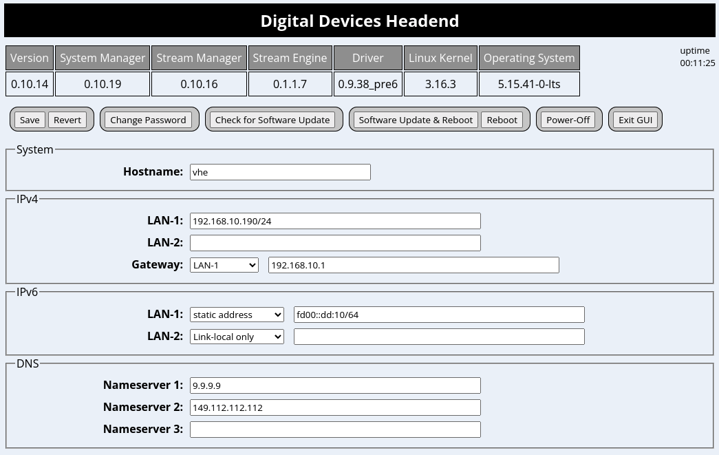
The host name should be set here. The name must begin with a lower case letter, followed by up to 15 lower case letters or numbers. Special characters are not allowed.
The IPv4 and IPv6 addresses can be set here for LAN-1 and/or LAN-2, as well as the address of the gateway.
One or more DNS server addresses must be entered in DNS. If no local DNS server is used, several public DNS servers can also be set via the menu button.
The configuration is saved with the Save button.
The headend can now be switched off and installed at its planned location.
A HDMI monitor, a USB keyboard and a USB mouse must be connected to the headend.
The graphical user interface is started by logging in with the user name admin.
The host name should be set first. The name must begin with a lowercase letter, followed by up to 15 lowercase letters or numbers. Other characters, including uppercase letters, are not permitted.
Now the IPv4 and IPv6 addresses can be set for LAN-1 and/or LAN-2, as well as the address of the gateway.
Save the data with Save and restart the system with Reboot.
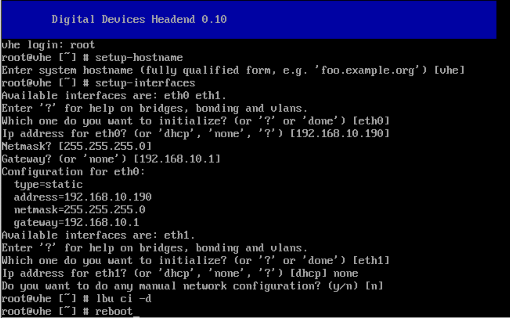
Login as root. There is no default password.
Use the command setup-hostname to set the hostname. The hostname must start with a lowercase letter and contain up to 15 lowercase letters or digits. Other characters, including uppercase letters, are not allowed.
Use the command setup-interfaces to configure the IPv4 address.
The command first ask for the name of the interface.
Enter eth0 for LAN-1 or eth1 for LAN-2.
Enter the IPv4 address for eth0 or eth1. Entering none removes the current address. Entering dhcp will be overwritten later by the administration software.
Enter the netmask and the gateway address.
Configure a second interface, or enter done to end the program.
Use the command lbu ci -d to save all changes permanently on disk.
Use the command reboot to reboot the device.

The Add Device button opens a window for entering another headend.
The IPv6 Discovery button starts IPv6 Discovery on the LAN.
The DVB-S Setup button opens the DVB-S window.
The Check for DDM software update button checks whether a new version of DDM is available.
The main window contains one line per headend.
The following data is stored locally:
The following data is stored on the headend:
Device Control contains the following fields:
Streaming contains the following fields:
Type contains the device type.
Status contains:
Context menu:
The connection to the headend can be activated/deactivated in the menu with “Connect” and “Disconnect” or by clicking on the status square.
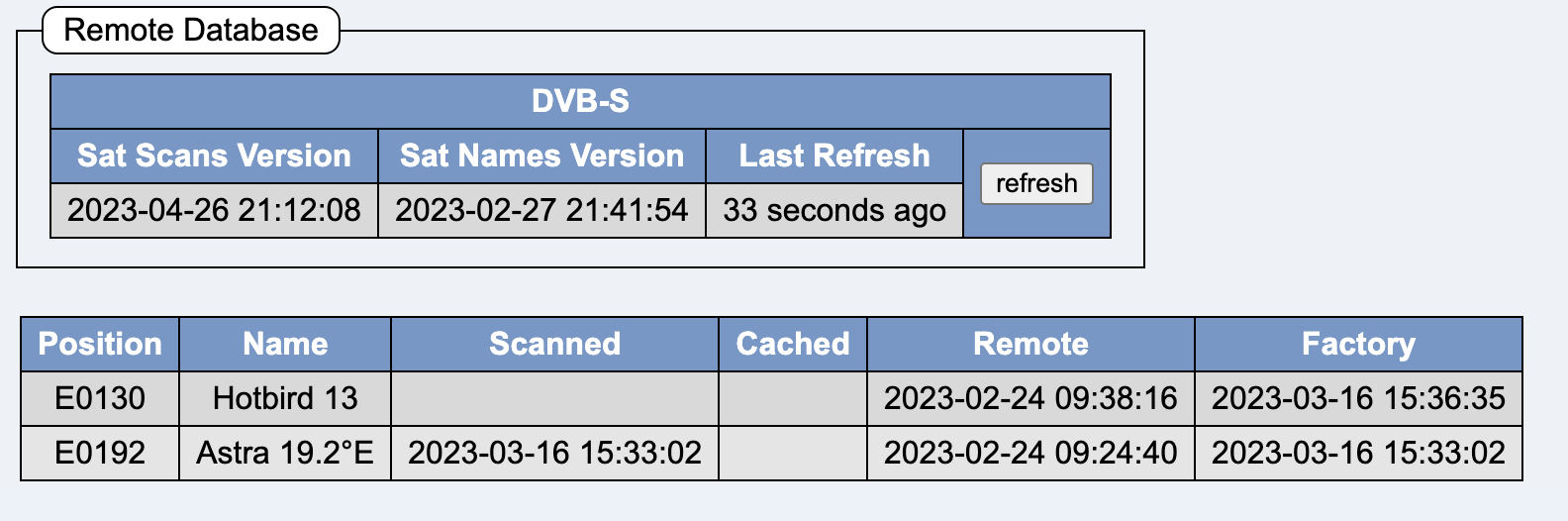
Context menu of a line in the satellite database:
Spectrum Scan:
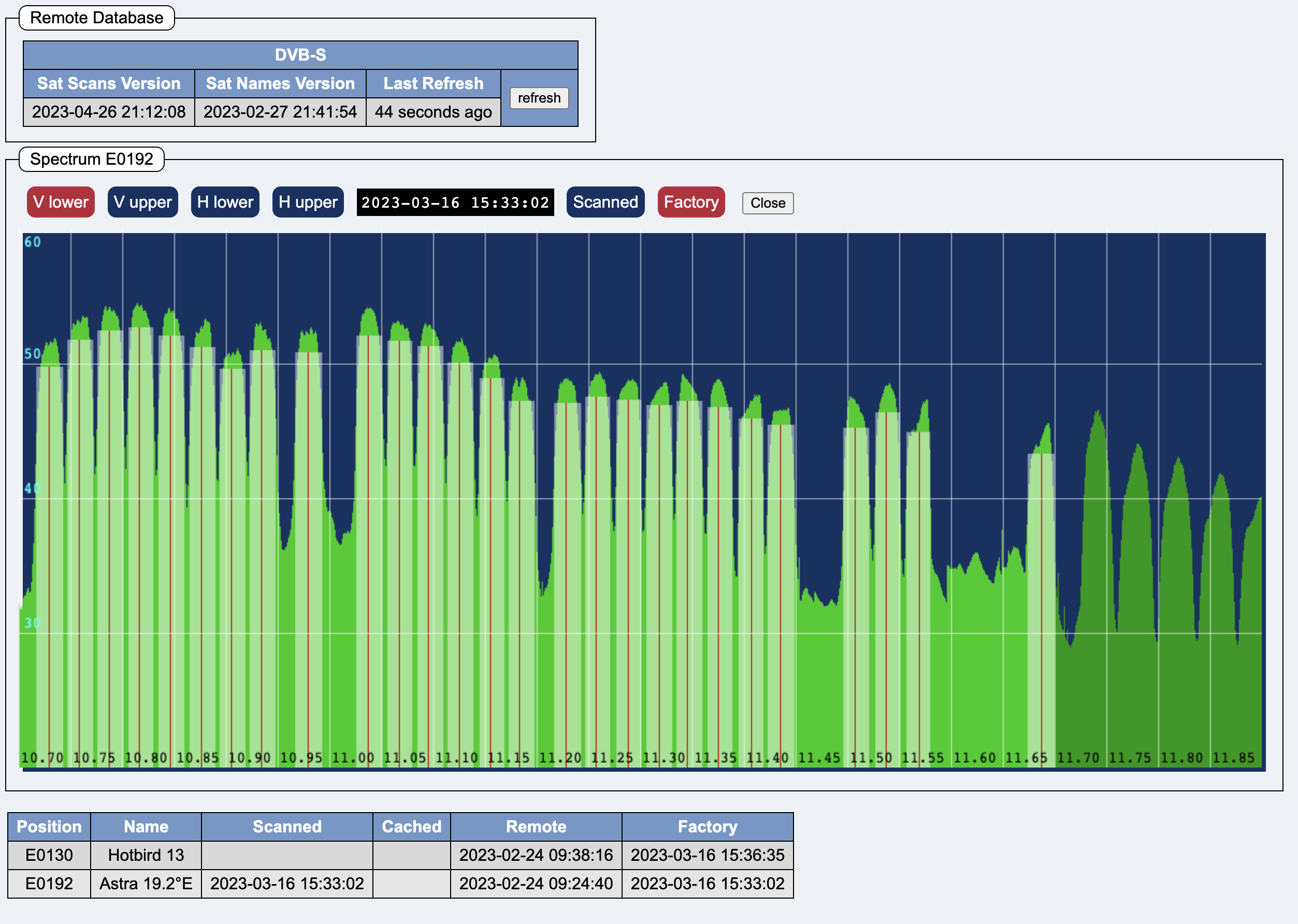
The buttons V lower V upper H lower H upper switch between the four bands.
The buttons Scanned Cached Factory switch between the self-scanned data, the download data and the factory data.
The Close button closes the spectrum scan.

The status box shows the connection status to the headend.
The tabs are explained in the following sections.
The Unicable tab is only shown, when Unicable has been configured on the Satellites tab.
The CAM tab is only shown, when CAM slots are present.
Reboot reboots the headend. The button cannot be clicked as long as changes have not yet been saved. If the button is outlined in red, then a reboot is needed to activate some changed parameters.
Save saves changes permanently, but the setup window remains open.
Save & Close saves changes permanently and closes the setup window.
Revert cancels all changes, but the setup window remains open.
Cancel cancels all changes and closes the setup window.
If changes have not been saved, the buttons have a yellow background: 
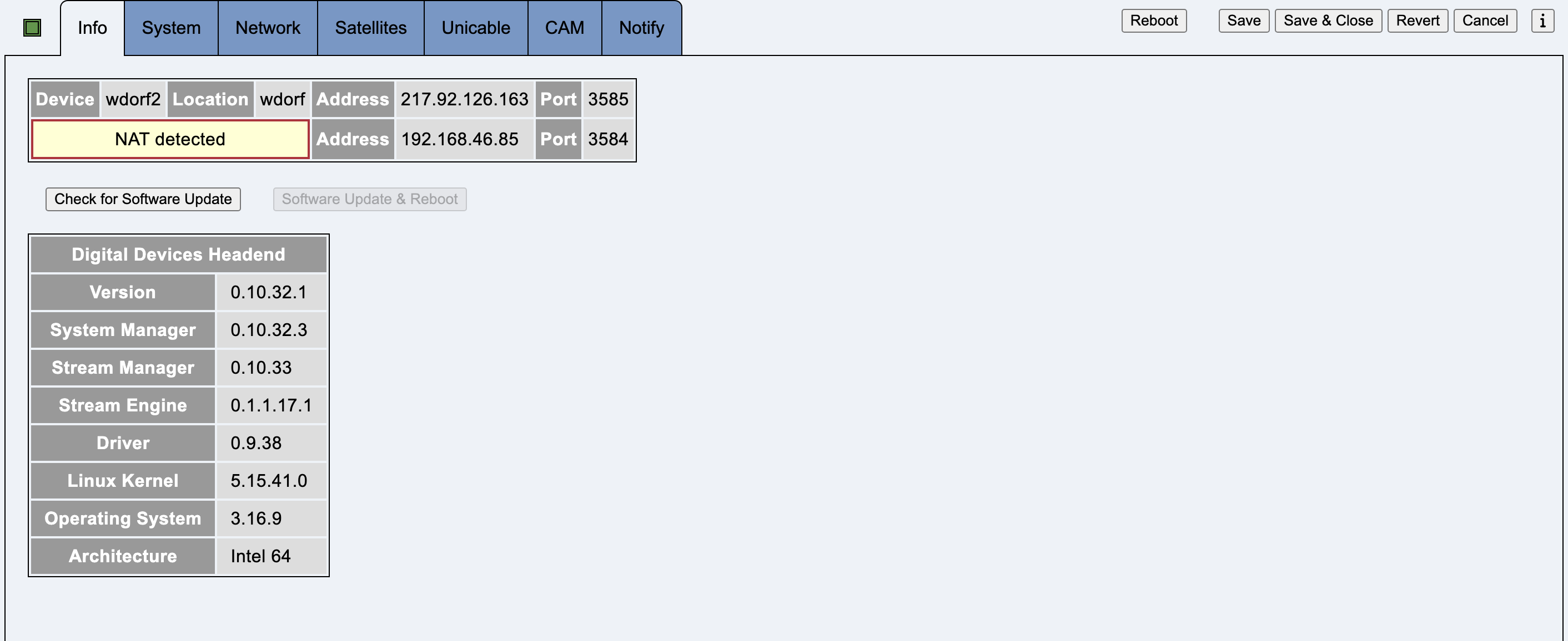
This tab contains information about the connection to the headend, as well as software and firmware version numbers.
The fields Device and Location are used to identify a headend if the DDM manages several headends. This data is only saved locally in the DDM, not on the headend.
Check for Software Update starts a software update check.
If a software update is possible, Software Update & Reboot becomes clickable and has a yellow or red background.
A green background means that an update should be carried out.
A yellow or red background means that a software update check should be carried out as soon as possible.
A green background means that the update is most likely possible without a reboot. Only individual components are restarted.
A yellow background means that the headend will be rebooted after the update.
A red background means that an update should be made as soon as possible.
After a successful firmware update, the headend must be switched off for three seconds. To do this, the plug must be pulled out of the socket. Using the On/Off switch on the front panel does not work.
(Intel Hardware only)
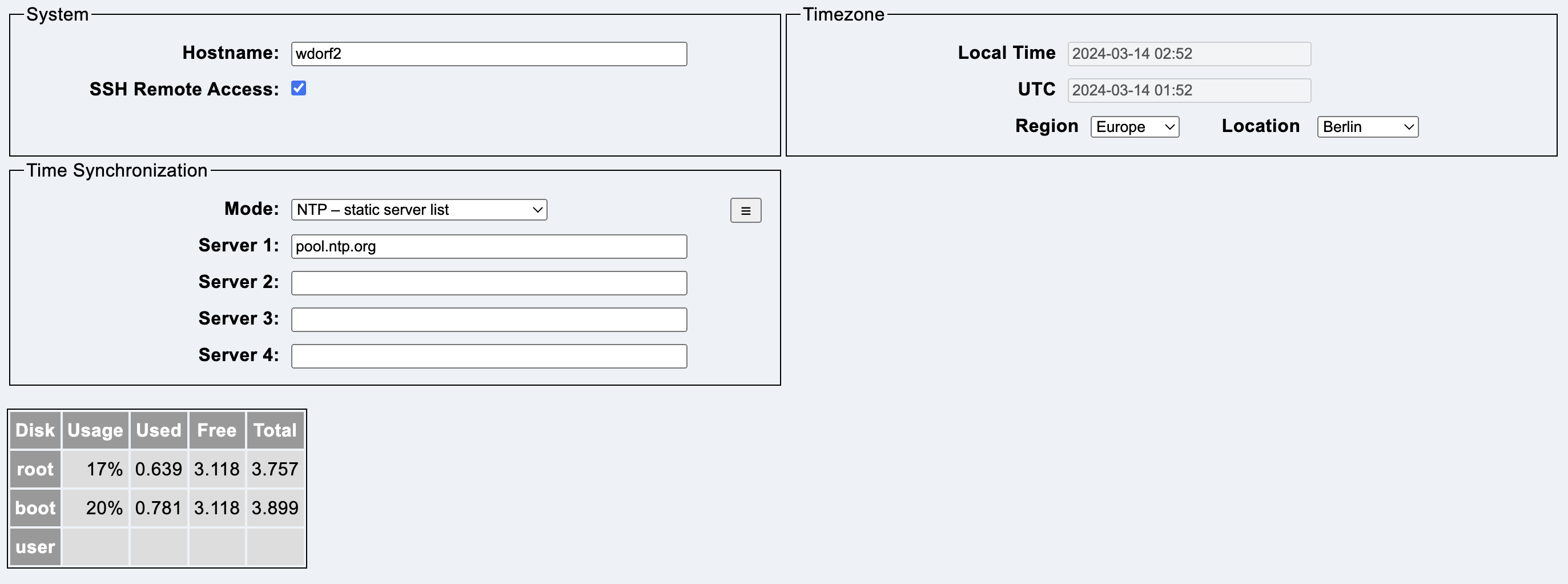
This tab contains the system configuration.
Hostname contains the name of the system. The name may consist of up to 15 lower case letters and numbers. The first character must be a letter.
SSH Remote Access allows access for the Digital Devices Service Team via the Internet. If this option is activated, the headend accepts SSH connections on port 22.
The following regions exist:
The list of time zones is specified by the operating system on the headend.
NTP is used to synchronize the time of the headend.
Up to four NTP servers can be entered. The fields can contain a domain or an IPv4 address.
The menu button allows a quick selection of public NTP servers.
The domain de.pool.ntp.org is recommended for operation in Germany.
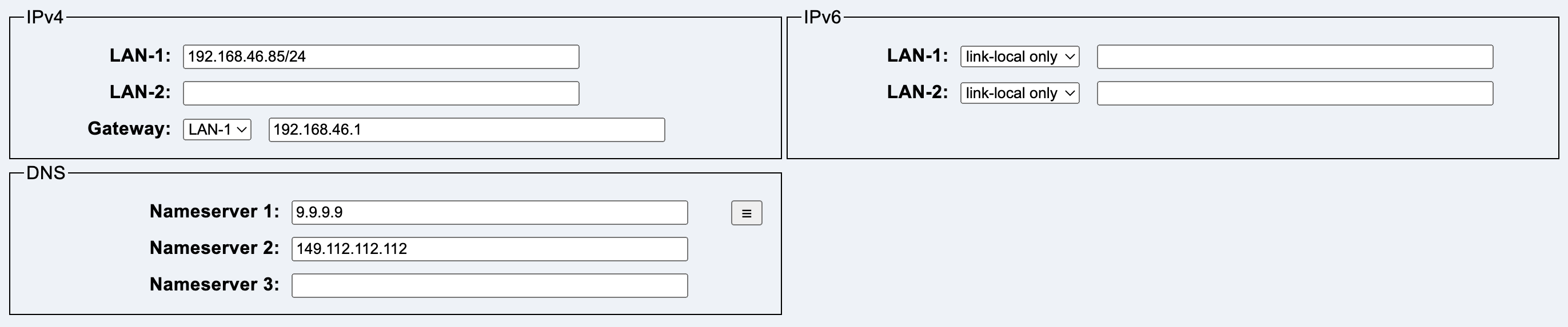
This tab contains the network configuration.
LAN-1 contains the IPv4 address including the subnet size, e.g. 192.168.1.1/24.
LAN-2 contains the IPv4 address including the subnet size, e.g. 10.4.2.6/8.
Gateway contains a combo box that can be used to select the interface on which the gateway is located, as well as the IPv4 address of the gateway.
One of the following operating modes can be selected for both interfaces:
The headend uses only the link-local address and does not listen to router announcements. Connections outside the LAN are not possible.
The headend automatically configures itself to the existing IPv6 network (SLAAC). Connections to the Internet are possible. However, incoming connections are not reliable, as the dynamic IPv6 address changes over time.
The headend is configured to a static IPv6 address. Outgoing and incoming connections to the Internet are possible if a global IPv6 address (2000::/3) is used. When using a private address (fd00::/8), the headend is not reachable from the Internet.
DNS contains up to three IP addresses of name servers.
The menu button allows the selection of public DNS servers.
No software update is possible without configured DNS servers.
This tab configures the satellite setup.
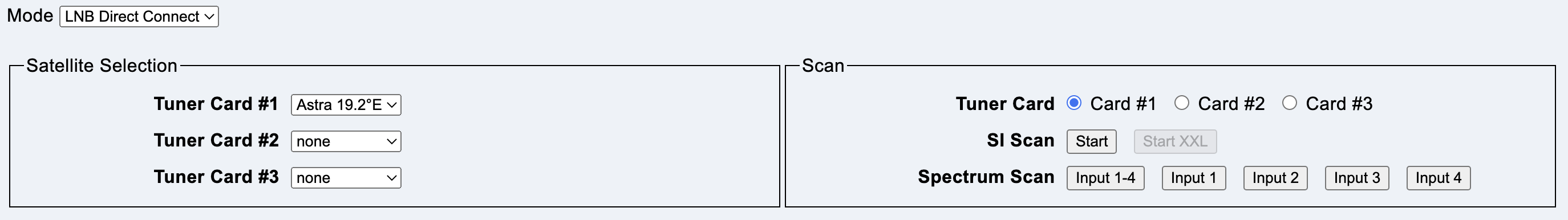
This mode is selected if a Quattro LNB is connected to all tuner cards.
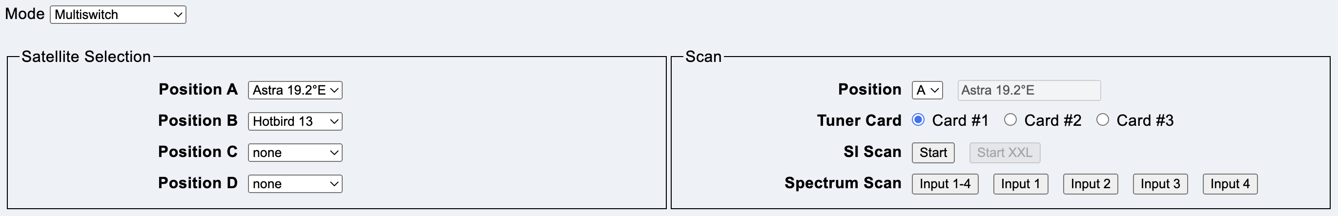
This mode is selected if a multiswitch or quad LNB is connected to all tuner cards.
The headend uses DiSEqC for selection.
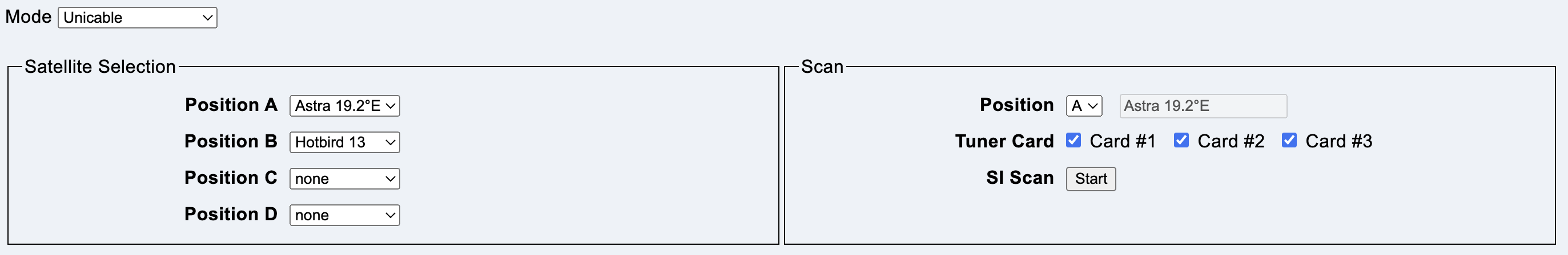
This mode is selected if a Unicable system is connected to all tuner cards.
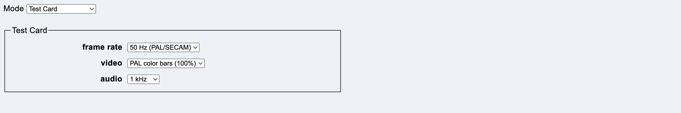
This mode sends a test image on all modulator channels.
The connected satellite is configured here for the tuner cards.
Only satellites whose data is available in the local database are displayed.
Unknown satellites must first be scanned using SI Scan.
The connected satellite is selected here for positions A, B, C and D.
Only satellites whose data is available in the local database are displayed.
Unknown satellites must first be scanned using SI Scan.
The scan mode is configured and started here.
Position selects the satellite position (Multiswitch and Unicable only). If the name of the satellite is known, it is displayed in the field behind it.
Tuner Card selects the tuner card on which the scan is to be performed.
Button Start starts a complete scan of a satellite. First a spectrum scan, to locate transponders, then a SI scan to find all satellite data. At the end of a successful scan, the data can be saved in the local database.
Button Input 1-4 starts a spectrum scan on all four inputs.
Buttons Input 1 Input 2 Input 3 Input 4 start a spectrum scan on the named input.
Note: Streaming is stopped during scanning.
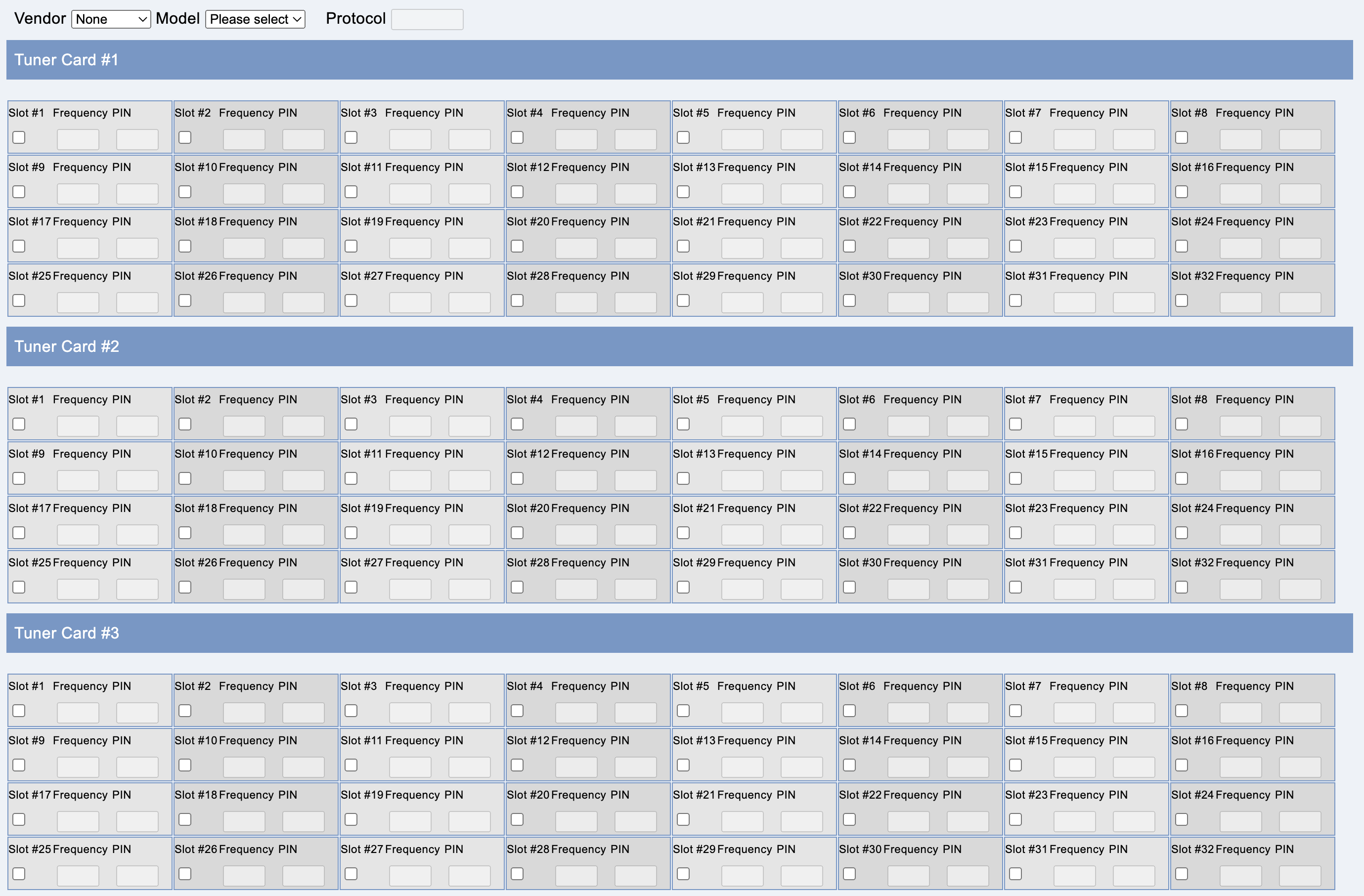
This tab contains the Unicable configuration and is only available, if Unicable is activated on the Satellite tab.
Vendor chooses the vendor of the unicable system, Model the device from that vendor. Protocol displays the protocol of the device.
You can choose the slot numbers for each tuner card.
Note: Unicable version 1 cannot feed all 24 tuners.
If a slot is activated on a tuner card, the field disappears from the view of the other tuner cards.
If a slot is activated on a tuner card and the Unicable system works with PINs, the PIN can be configured. Values from 0 to 255 are possible. An empty field deactivates the PIN.
In “Custom” mode, the frequency can be set for an activated slot. Values from 950 to 2150 are possible (MHz). The value 0 or an empty field indicates a slot that cannot be used.
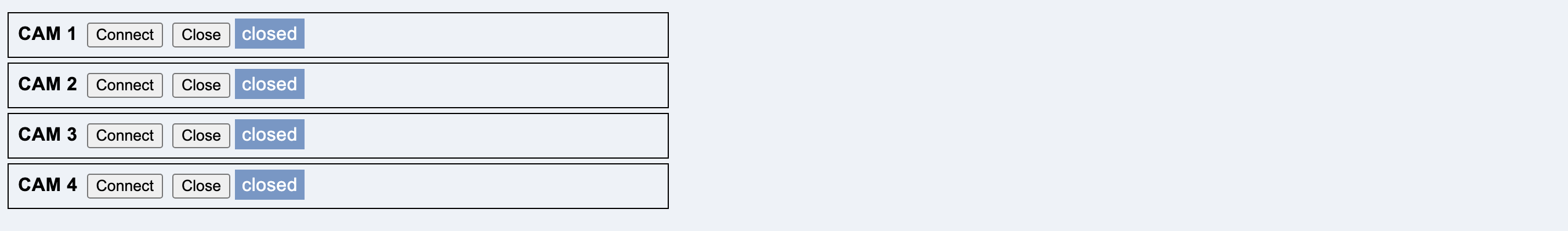
This tab is only displayed if CAM slots are present.
Connect establishes a connection to the corresponding CAM.
Close closes the connection to the corresponding CAM.
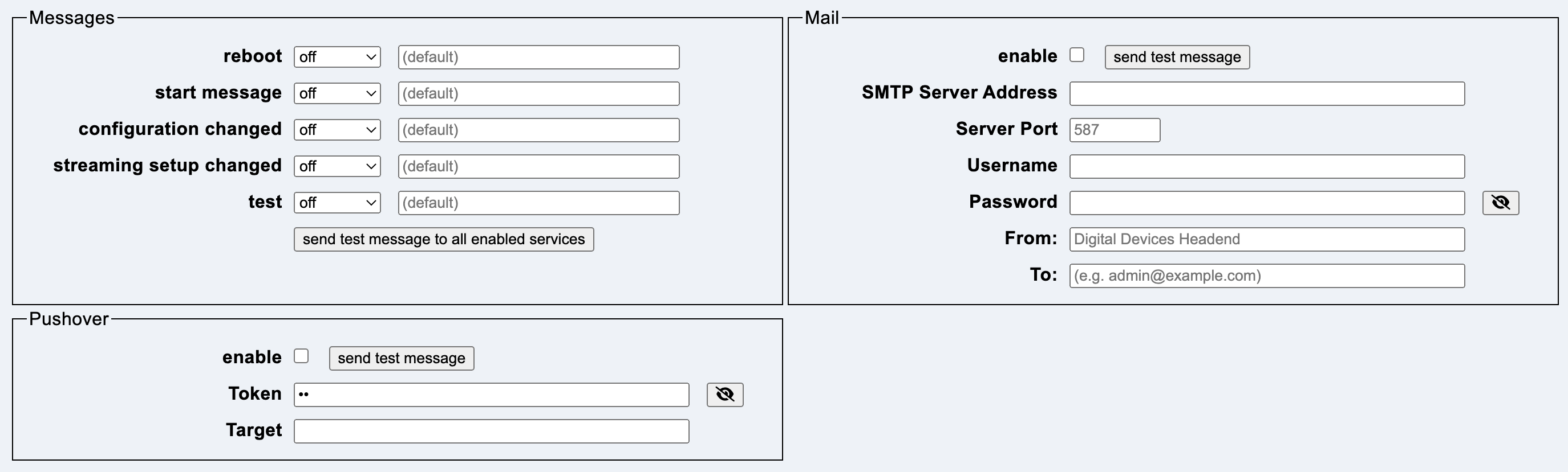
This tab contains options to notify admins when certain events are triggered on the headend.
There are five categories of messages:
Each category has a priority:
The button send test messages to all enabled services sends the test event to all active services.
The sending of mails is configured here.
SMTP Server Address contains the IP address of the local SMTP server.
Server Port is the port number for delivering the mail. The default is 587.
Username and Password contain information if authentication is required.
From contains the sender address. The default is the host name with the addition “(Digital Devices Headend)”.
To contains the list of destination addresses, separated by a comma or space.
Sending via the https://pushover.net service is configured here.
Token contains the API token/key of the application.
Target contains the group key or the user key of the target.
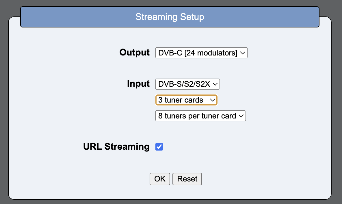
The Stream Editor is used to configure the DVB services.
It can be started in several ways.
selecting New in the File Menu
New in the device overview
A dialog box appears where you can select the number of DVB-S tuner cards and the number of DVB-C/-T modulators.
The current status is read from the headend. DDM must be connected to the headend and the streamer must be active on the headend.
The number of DVB-S tuner cards and the number of DVB-C/-T modulators are configured in a dialog.
This tab contains parameters for NIT and TOT.
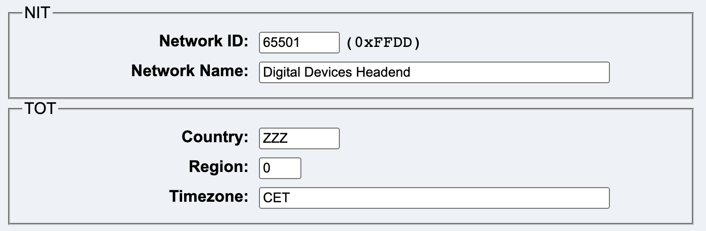
Network ID is a value from 1 to 65535. The values from 1 to 65279 are officially assigned. The values from 65280 to 65535 are reserved for private use.
Network Name contains the name of the network. Only US-ASCII characters should be used.
Country is the country code. It consists of exactly three uppercase letters. The default value is “ZZZ”.
Region is a region ID. The value range is from 0 to 63. The default value is “0”.
Timezone is the internal name of the time zone. The default value is “CET”.
Errors that occurred when reading from the headend are displayed here.
If an error occurs, this tab is initially shown.
If only warnings occur, the Services tab is initially shown.
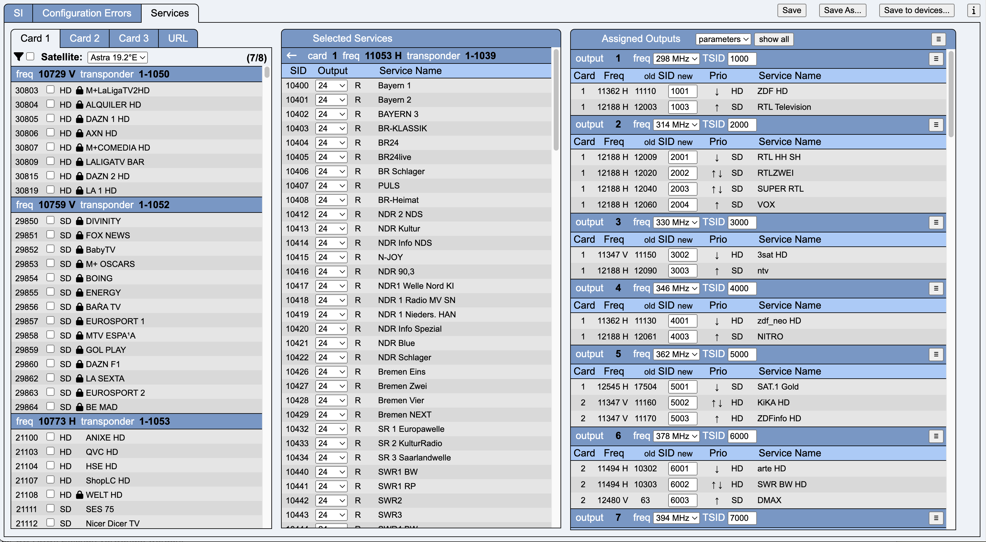
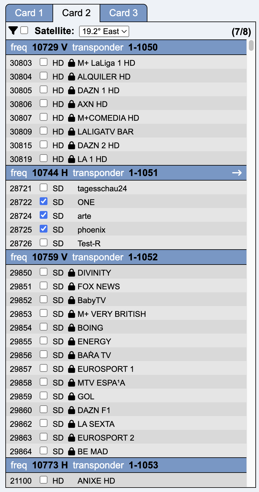
This tab is used for service parameter configuration.
This column is used to select the required services.
The transponders are listed sorted by frequency. In addition to frequency and polarization, the Network ID and the Transponder Stream ID are also displayed.
The services of a transponder are sorted by Service ID (first column). The checkbox selects a service, which is then immediately displayed in the next column (Selected Services).
The white right arrow in the transponder can be used to scroll directly to the corresponding transponder entry in the middle column.
When the filter is activated (checkbox next to the filter symbol), the filter options appear.
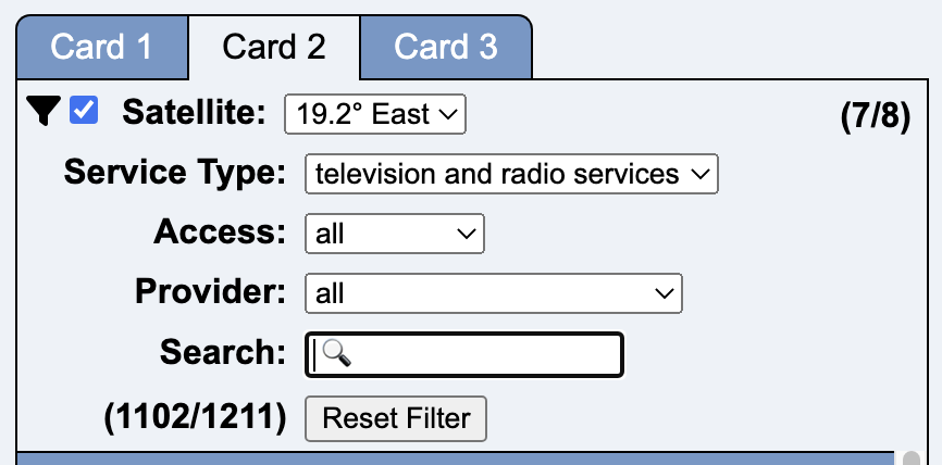
Service Type allows filtering according to specific services.
Access has the following selection:
With Provider you can search for all services of a specific provider. Since there are unfortunately typing errors and different views of capitalization, it is possible that a provider is represented with several similar entries.
Search is a free search mask where you can search by name, provider, service IDs and frequencies.
This column shows the services selected in the left-hand column, sorted by tuner card and transponder frequency.
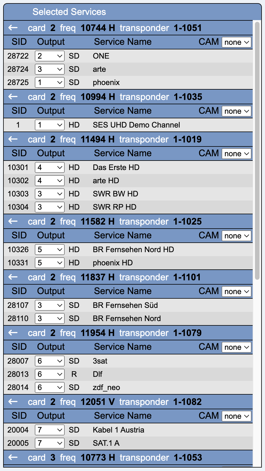
Output selects one of the output channels / modulators.
CAM selects one of the four available CAMs for decoding. A CAM can only be active on a single transponder. However, the entire transponder is not decrypted, but the encrypted services must be explicitly marked for decryption using the checkbox.
This column is sorted according to the output modulators.
The global menu button offers the following options:
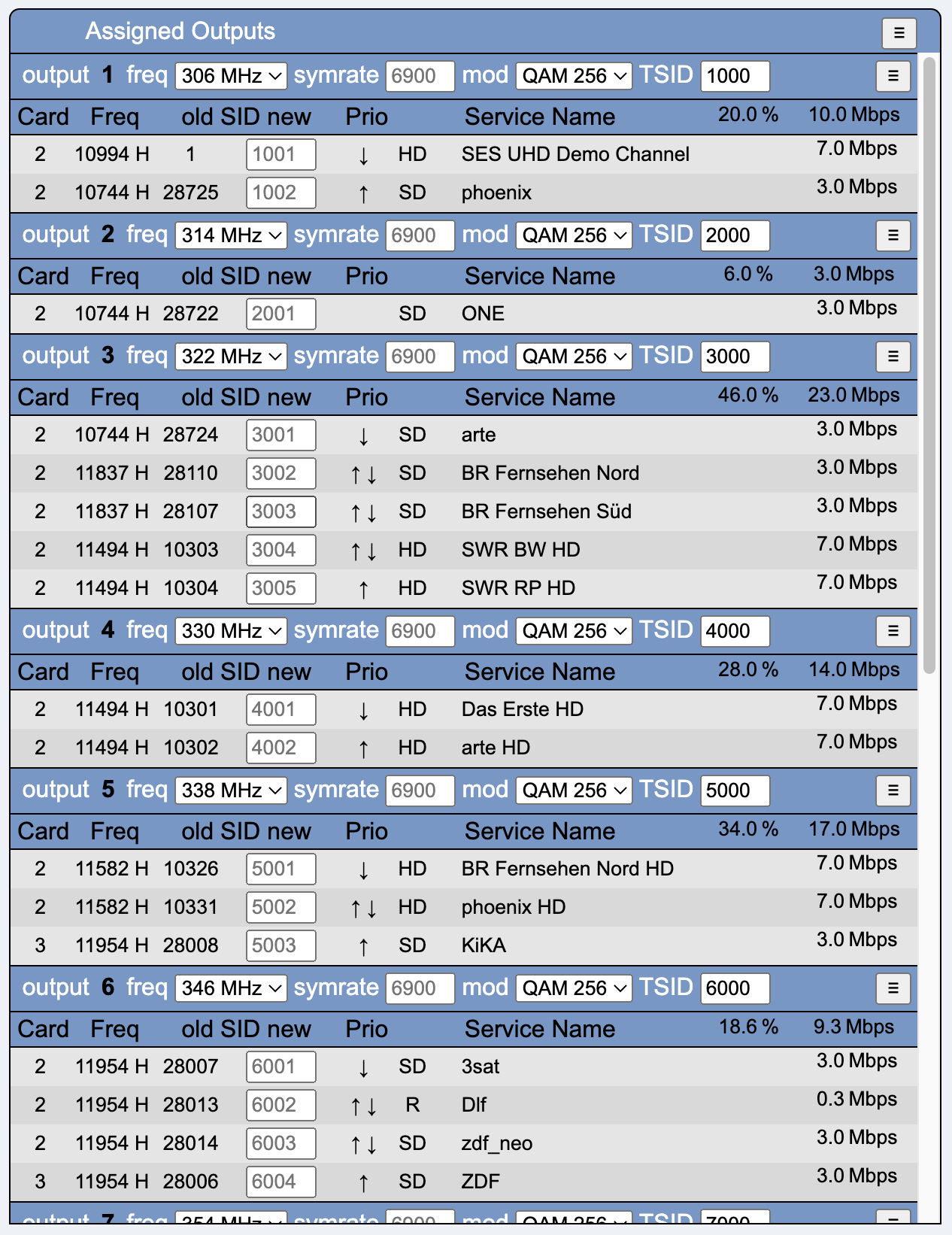
freq selects the DVB-C frequency of the modulator. This frequency can only be active on one modulator.
symrate is the symbol rate. Default is 6900.
mod is the selection of the modulation method. Default is QAM 256.
tsid is the transport stream ID of the modulator.
The menu button in Output offers the following options:
(Output n)
(All Outputs)
Card contains the ID (1, 2 or 3) of the tuner card
Freq contains the input transponder frequency and polarization
old SID new contains the original SID and a field for entering an output SID. The default is the input SID.
Prio is a priorization of the services. If the bandwidth on the output becomes scarce, low-priority services are deactivated. The list can be sorted manually using the arrows.